

Waveshare has announced its BG95-M3 Zero, a single-board computer (SBC) that offers cellular connectivity as well as compatibility with Raspberry Pi HAT add-ons. It features its own processor and ships with Quectel’s QuecPython MicroPython firmware for easy programming.
The BG95-M3 Zero is in a Raspberry Pi Zero form factor (65 x 30 mm) and integrates an Arm Cortex-A7 processor running ThreadX RTOS. Most Quectel modules for cellular Internet of Things (IoT) usage depend on another board for a host processor. This allows hobbyists and IoT manufacturers to develop smaller smart products with cellular capabilities since there’s no need for an additional SBC to run the show.
This development board is equipped with a BG95-M3 module, which supports LTE Cat M1, LTE Cat NB2, and EGPRS cellular networking worldwide. It also supports GNSS positioning using GPS, GLONASS, BDS, Galileo, and QZSS. The SBC includes an onboard nano SIM card slot positioned near the edge of the board for easy insertion and removal.
| Header Cell – Column 0 | BG95-M3 Zero | EC200U-EU | EC200U-AU |
|---|---|---|---|
| LTE-FDD | Cat M1: B1, B2, B3, B4, B5, B8, B12, B13, B18, B19, B20, B25, B26, B27, B28, B66, B85 | B1, B3, B5, B7, B8, B20, B28 | B1, B2, B3, B4, B5, B7, B8, B28, B66 |
| Row 1 – Cell 0 | Cat NB2: B1, B2, B3, B4, B5, B8, B12, B13, B18, B19, B20, B25, B28, B66, B71, B85 | Row 1 – Cell 2 | Row 1 – Cell 3 |
| LTE-TDD | N/A | B38, B40, B41 | B38, B40, B41 |
| GSM/GPRS/EDGE | 850, 900, 1800, 1900 MHz | GSM: B2, B3, B5, B8 | GSM: B2, B3, B5, B8 |
| Maximum Downlink/Uplink Speeds (LTE) | Cat M1: DL: 588Kbps; UL: 1119Kbps | LTE-FDD: DL 10 Mbps; UL 5 Mbps | LTE-FDD: DL 10 Mbps; UL 5 Mbps |
| Row 5 – Cell 0 | Cat NB1: DL 32 Kbps; UL 70 Kbps | LTE-TDD: DL 8.96 Mbps; UL 3.1 Mbps | LTE-TDD: DL 8.96 Mbps; UL 3.1 Mbps |
| Row 6 – Cell 0 | Cat NB2 – DL: 127 Kbps; UL: 158.5 Kbps | Row 6 – Cell 2 | Row 6 – Cell 3 |
| Maximum Downlink/Uplink Speeds (GSM/GPRS/EDGE) | EDGE: DL 296 Kbps; UL 236.8 Kbps | GSM: DL 85.6 Kbps; UL 85.6 Kbps | GSM: DL 85.6 Kbps; UL 85.6 Kbps |
| Row 8 – Cell 0 | GPRS: DL 107 Kbps; UL 85.6 Kbps | Row 8 – Cell 2 | Row 8 – Cell 3 |
| GNSS | GPS, GLONASS, BDS, Galileo, QZSS | GPS, GLONASS, BDS, Galileo, QZSS | GPS, GLONASS, BDS, Galileo, QZSS |
| Bluetooth | N/A | Bluetooth 4.2 (BR/EDR) | Bluetooth 4.2 (BR/EDR) |
| Wi-Fi Scan | N/A | 2.4 GHz 11b (Rx) | 2.4 GHz 11b (Rx) |
A group of five LEDs on the board indicate operating status. These include power, sleep, and network indicators. There’s also an LED that illuminates when a SIM card is inserted as well as a PWM function indicator.
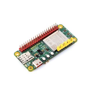
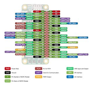
The Waveshare BG95-M3 Zero has a 40-pin GPIO header and a USB Type-C port for flashing the firmware. The BG95-M3 Zero integrates an onboard MIPI interface for connecting to MIPI displays and Raspberry Pi peripheral devices. The board also has an onboard camera interface to support customized SPI cameras up to 30MP.
While the BG95-M3 Zero doesn’t offer Bluetooth or Wi-Fi support, Waveshare does produce larger boards with expanded networking capabilities. The EC200U-EU is available in Europe, the Middle East, Africa, Australia, New Zealand, and Brazil. There’s also the EC200U-AU available in Australia and Latin America.
| Header Cell – Column 0 | BG95-M3 Zero | EC200U-EU, EC200U-AU |
|---|---|---|
| Type-C USB Port | Supports AT commands testing, GNSS positioning, firmware upgrading, etc. | Supports AT commands testing, GNSS positioning, firmware upgrading, etc. |
| Communication protocol | PPP, TCP, UDP, SSL, TLS, FTP(S), HTTP(S), NITZ, PING, MQTT, LwM2M, CoAP, IPv6 | TCP, UDP, PPP, NITZ, PING, FILE, MQTT, NTP, HTTP, HTTPS, SSL, FTP, FTPS, CMUX, MMS |
| SIM card | Nano SIM card (supports 1.8V only) | Nano SIM and eSIM, dual card single standby |
| Indicator | SIM_CHK: lights up when a SIM card is inserted into the card slot | P01: Module Pin 1, default as EC200A-XX PWM0 |
| Row 4 – Cell 0 | NET: Network indicator | P05: Module Pin 5, NET_MODE indicator |
| Row 5 – Cell 0 | PSM: Sleep indicator | SCK1: SIM1 detection indicator, lights up when SIM1 card is inserted |
| Row 6 – Cell 0 | PWM: PWM function indicator | SCK2: SIM2 detection indicator, lights up when SIM2 card is inserted |
| Row 7 – Cell 0 | PWR: Power indicator | PWR: Power indicator |
| Buttons | PWK: Power ON/OFF | PWK: Power ON/OFF |
| Row 9 – Cell 0 | PON: PSM wake-up | RST: Reset |
| Row 10 – Cell 0 | BOOT: Forcing into firmware burning mode | BOOT: Forcing into firmware burning mode |
| Row 11 – Cell 0 | USB ON/OFF: USB power consumption detection switch | USB ON/OFF: USB power consumption detection switch |
| Antenna Connectors | LTE main antenna + DIV antenna + GNSS antenna | LTE main antenna + DIV / WIFI (scanning only) / Bluetooth antenna + GNSS antenna |
| Operating Temperature | -30 ~ 75°C | Row 13 – Cell 2 |
| Storage Temperature | -45 ~ 90°C | Row 14 – Cell 2 |
Programming the SBC is done through QPYcom, a specialized development and debugging tool for QuecPython. QPYcom is Windows-only, but Waveshare notes that you can use plugins for Thonny IDE. VSCode, and other IDEs to program the board.
This post was originally published on the 3rd party mentioned in the title ofthis site